What Is an RMU Electrical Panel and How Does It Work?
A Rmu Electrical Panel, more commonly called a ring main unit (RMU), is compact medium-voltage switchgear used to control and protect local power distribution. It can connect a transformer to a ring-shaped network, helping operators isolate a faulty cable section while keeping other sections supplied. Inside the metal enclosure, busbars link switching devices, while load-break switches, circuit breakers, or fuses perform different switching and protection duties. The exact arrangement varies by voltage, utility practice, and equipment design. Small details matter.
The need for dependable distribution equipment is growing. The International Energy Agency’s Electricity Grids and Secure Energy Transitions (2023) estimates that 80 million kilometres of grids must be added or replaced by 2040, roughly the length of the existing global grid. That projection concerns grids overall, not RMU demand specifically, but it shows why reliable switching and fault isolation matter. Faults happen. In practice, an operator may use an RMU to disconnect the damaged feeder, verify the switching position, and restore service through an alternate route when the network allows it. IEC 62271-200 sets requirements for certain high-voltage metal-enclosed switchgear, but readers should check the equipment’s rated voltage and applicable specification rather than assume every RMU is identical. This guide explains the main components, switching sequence, and protection role of an RMU, while noting where designs differ. One point deserves care: compact equipment can simplify installation, but it does not remove the need for trained operation, maintenance, and site-specific safety procedures.
What an RMU Electrical Panel Is and What It Does
An RMU, or ring main unit, is compact medium-voltage switchgear used in electrical distribution networks. It connects incoming and outgoing cables and provides a protected connection to a local transformer. In practical terms, it is often installed in a roadside cabinet or a building’s electrical room. Not a transformer. Its job is to control and protect the circuits around one.
Inside the enclosure, switches let trained operators isolate cable sections for inspection or repair. A circuit breaker or fuse can disconnect a transformer branch when a fault occurs. This helps limit outages to the affected section, while other parts of the ring may remain supplied. The exact arrangement varies by network and equipment design. An RMU does not prevent every outage.
The IEA’s 2023 Electricity Grids and Secure Energy Transitions report puts annual grid investment at roughly $300 billion. It says investment must exceed $600 billion by 2030. That is a grid-wide estimate, not a forecast for RMU demand. Still, it shows the scale of network upgrades underway. When selecting or assessing an RMU, engineers consider voltage, fault levels, cable layout, protection settings, and maintenance access. The details matter. A compact cabinet can simplify installation, but cramped access can make inspection harder.
Key Components Inside an RMU Electrical Panel
Key Components Inside an RMU Electrical Panel
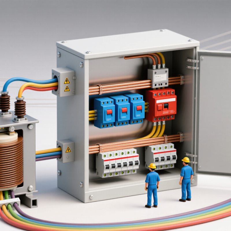
An RMU brings several medium-voltage switching functions into a compact enclosure. Copper busbars connect incoming and outgoing circuits. A load-break switch handles normal switching, while a circuit breaker may provide fault interruption. Some configurations use fuses instead. The exact arrangement depends on the network and protection design.
Insulation separates live conductors from the grounded enclosure. It may use gas, solid materials, or air, depending on the equipment. For gas-insulated units, the environmental detail matters:
The IPCC Sixth Assessment Report gives sulfur hexafluoride a 100-year global warming potential of 25,200 times carbon dioxide. Not every RMU uses this gas.
Cable terminations, current transformers, and voltage sensors support connections and measurement. Earthing switches ground isolated sections during maintenance.
Interlocks help prevent unsafe switching sequences, but they cannot replace trained operating procedures. IEC 62271-200 sets requirements for metal-enclosed switchgear above 1 kV and up to 52 kV.
Small parts matter. A neat diagram can still hide weak labeling or an overlooked interlock check. Inspect indicators, cable connections, and operating mechanisms according to the equipment’s maintenance instructions.
How an RMU Connects and Distributes Electrical Power
An RMU, or ring main unit, links medium-voltage cables and directs power to local transformers. Inside its enclosure, switches or circuit breakers control incoming and outgoing feeders. A separate branch usually supplies a transformer, which steps voltage down for nearby buildings. Simple in principle.
In a ring network, power can reach a supply point from either direction. If a cable section develops a fault, operators can isolate that section and restore supply through the alternate route, where the network design permits. Earthing switches help make isolated equipment safe for maintenance. The actual sequence depends on protection settings and the site’s switching plan; a single diagram rarely shows every operating constraint. IEC 62271-200 sets requirements for metal-enclosed switchgear in this voltage range. The wider need for dependable equipment is growing: the IEA’s 2023 report, Electricity Grids and Secure Energy Transitions, says annual grid investment must rise from about USD 300 billion to over USD 600 billion by 2030. That figure covers grids broadly, not RMUs alone, but it underscores why reliable switching and clear fault isolation matter.
What Is an RMU Electrical Panel and How Does It Work?
An RMU (ring main unit) connects incoming and outgoing medium-voltage cables through a busbar and switching devices. It can keep a ring network connected while isolating a section for maintenance or a fault, and its transformer feeders distribute power to local loads.
Example: The chart estimates three-phase line current from transformer nameplate capacity using I = S ÷ (√3 × V), with V = 11 kV. These are illustrative feeder ratings, not measured operating loads; actual current depends on the connected load.
How Switching and Fault Isolation Work
An RMU electrical panel controls connections in a medium-voltage ring network. Its switches let operators connect or disconnect feeder cables and transformers. During normal operation, current may pass through the ring along an established route. The metal enclosure keeps live components contained, while internal insulation and interlocks support safe operation. Details vary by design.
When a cable fault occurs, protection equipment detects abnormal current and signals the relevant breaker or fuse to interrupt it. Operators then open switches to separate the damaged section from the rest of the network. The aim is to isolate only the faulted part, so unaffected loads may receive power from another route if the network permits. That matters.
Switching is not just a matter of moving a handle. Operators follow the approved switching sequence, check position indicators, and use appropriate safety procedures. Some RMUs use load-break switches for routine switching, while a circuit breaker handles fault interruption. Those functions are not interchangeable. A mimic diagram can make the process look simple, but actual conditions may differ from the drawing. Careful verification is essential. Even a small mistake can leave equipment energized or interrupt more customers than intended.
Where RMUs Are Used and How They Are Kept Safe
RMUs are compact medium-voltage switchgear units used to connect and protect sections of an electrical distribution network. They are common in urban substations, apartment complexes, hospitals, factories, and other sites where reliable power must fit into limited space. Some renewable-energy installations use them to connect equipment to local distribution networks. Space is limited. Their exact layout varies, so not every unit contains the same switches or protective devices.
An RMU typically provides switching points for incoming and outgoing cables, with protection for a transformer or feeder. Depending on its design, protection may use a circuit breaker or fuses. Operators can isolate a section during maintenance or when a fault occurs, helping keep other parts of the network in service. That matters. But switching sequences differ between installations, and a diagram alone may not show the equipment’s current condition.
Safety depends on trained personnel, clear procedures, and equipment kept in good condition. Interlocks help prevent certain unsafe operations, while earthing switches provide a means to ground isolated equipment. Before work begins, qualified workers follow site procedures to isolate the relevant circuit and verify it is de-energized. They also check labels, cable records, and the unit’s condition. Dust, moisture, or unclear labeling can complicate a task more than expected. Routine inspections should follow the equipment instructions and site requirements; an RMU’s enclosed construction does not make it maintenance-free.