
Employment Application Apply
A Sheet Metal Die Cutting Machine uses a matched punch and die to shear sheet material into a required shape. Depending on its tooling and setup, it can blank parts, pierce holes, or cut slots. The press may be mechanical, hydraulic, or servo-driven. The right choice depends on the material, thickness, part geometry, production volume, and required tolerances.
The scale of the wider industry helps explain why these machines matter. World Steel Association’s World Steel in Figures 2024 reports that global crude steel production reached 1,888.2 million tonnes in 2023. That figure describes steel production, not demand for die-cutting equipment. Still, it shows the enormous material base served by forming and cutting processes. Automation is also expanding: the International Federation of Robotics’ World Robotics 2024 report counted about 4.28 million industrial robots operating in factories worldwide in 2023. Robots do not replace every press, but they can support loading, unloading, and part handling.
The details matter. “Die cutting” is not always used consistently; some suppliers use it broadly for press-based blanking and punching. That can make machine comparisons confusing. This guide explains how the process works, which machine types and tooling are commonly used, and what to check before selecting equipment. It also considers accuracy, cycle time, maintenance, and production limits. A fast machine is not automatically the right one. Tool wear, setup quality, and material variation can change results—and deserve more attention than a brochure usually gives them.
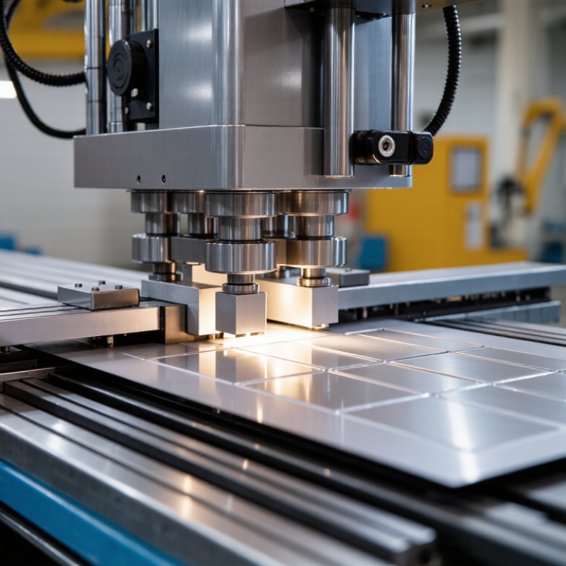
A sheet metal die cutting machine is a press that uses a shaped tool to cut or form sheet material. Its upper tool, called a punch, moves toward a matching lower die. The sheet sits between them, and press force separates a blank or creates features such as holes and notches. A clean edge matters. The machine’s core purpose is to produce repeated parts with consistent dimensions and predictable output.
In practice, the result depends on more than press force. Die clearance must suit the metal’s type and thickness; poor clearance can leave rough edges or accelerate tool wear. Operators also check alignment, feeding, and finished parts during production. For example, a small burr on a punched hole may signal a worn edge or an incorrect setup. Small changes matter. A die cutting machine can make parts quickly, but it cannot correct a flawed die design or careless setup. The practical definition includes both the press and the matched tooling, plus the adjustments that keep each cut within specification. Even a well-tuned process needs regular inspection; that part is easy to underestimate.
What Is a Sheet Metal Die Cutting Machine?
Main Components and Their Functions
A sheet metal die cutting machine uses a press and matched tooling to cut or form flat metal sheets. Its rigid frame supports the working force and helps keep the tooling aligned. The ram, or slide, moves the upper tool toward the lower tool with a controlled stroke. The die set holds both halves in position. Alignment matters.
A punch creates the cut or feature, while the die opening supports the sheet and defines the cut’s shape. A stripper plate holds the material flat and releases it from the punch as the ram rises. A feed system guides each sheet or coil into the work area. For repeat jobs, consistent feeding helps maintain part dimensions, though small setup errors can still accumulate.
Controls let operators adjust stroke, speed, and cycle settings. Guards and sensors help prevent access to moving parts during operation. Lubrication reduces friction on moving surfaces, and regular checks can reveal loose fasteners or uneven tool wear. There is no universally ideal setup; material thickness and feature geometry change the tooling choice. A careful test cut is useful, but it does not replace routine inspection.
| Component | What It Is | Main Function | How It Supports Cutting |
|---|---|---|---|
| Frame | The machine’s rigid structural body, commonly built as a gap-frame or straight-side frame. | Supports the press mechanism and withstands the forces generated during each stroke. | Maintains alignment and helps limit deflection under load, which is important for consistent cutting. |
| Drive system | A mechanical, hydraulic, or servo-based system that supplies motion and force. | Moves the slide through its operating cycle. | Provides the controlled force and motion needed to drive the punch into the sheet and through the die opening. |
| Slide (ram) | The moving press member connected to the drive system. | Carries the upper tooling and moves toward and away from the work area. | Transfers press motion to the punch and other upper die components. |
| Bolster plate and bed | The stationary support surface beneath the die, attached to the press frame. | Supports and locates the lower tooling. | Provides a stable base for the die and helps keep the tooling aligned with the slide. |
| Die set | A matched assembly of upper and lower die shoes, often guided by posts and bushings. | Holds and aligns the cutting components. | Guides the punch and die opening into the correct relationship during the stroke. |
| Punch | A shaped tool attached to the upper portion of the die. | Enters the sheet metal to form a cut, such as a hole or a blanked profile. | Works against the die opening to shear the material along the intended cutting edge. |
| Die opening (die button) | The shaped opening or lower cutting member that matches the punch profile. | Provides the opposing cutting edge and clearance for the cut material. | Allows the sheared slug or blank to pass through or be removed from the tooling. |
| Stripper plate | A plate surrounding or positioned near the punch, depending on the die design. | Holds or guides the sheet during cutting and removes it from the punch on the return stroke. | Helps prevent the sheet from lifting with the punch and supports repeatable feeding. |
| Material feeder | A manual or powered device that advances sheet, strip, or coil stock into the die area. | Positions fresh material for each press cycle. | Controls feed length and helps maintain consistent spacing between cuts in production work. |
| Controls and operating system | The buttons, control circuitry, and settings used to operate and monitor the press. | Manages operating modes, cycle commands, and machine status. | Allows operators to control press operation and coordinate the press with feeding equipment where fitted. |
| Safety devices | Protective equipment such as guards, interlocks, and presence-sensing devices. | Help reduce access to hazardous moving parts during operation. | Support safer operation when selected, installed, and used according to the machine’s design and applicable requirements. |
What Is a Sheet Metal Die Cutting Machine?
How the Die Cutting Process Works
A sheet metal die cutting machine uses a press and matched tooling to cut flat stock into parts. The sheet or coil feeds between a punch and die. When the press closes, the punch shears the metal against the die opening. Correct clearance helps control edge quality and tool wear. Small details matter. A narrow burr can affect assembly, while a worn punch may leave rough edges.
In a progressive die, the strip advances through stations for operations such as piercing, blanking, and forming. Each press stroke moves the part one step closer to its final shape. The World Steel Association’s World Steel in Figures 2024 reports 1,892.2 million tonnes of global crude steel production in 2023. That figure reflects the scale of steel supply, not die-cutting output; actual results depend on alloy, thickness, tooling, and setup. Real production is less tidy than a diagram. Coil variation and tool wear can change results, so operators inspect parts during the run.
Tips: Check the first parts for burrs and dimensional accuracy. Watch the burr. If it changes, pause and inspect the tooling before continuing.
A sheet metal die cutting machine presses a shaped tool into flat stock to cut or form repeatable parts. Common cutting dies include blanking dies, which produce the finished outline, and piercing dies, which punch holes. Compound dies perform several cutting operations in one press stroke. Progressive dies move a strip through stations, adding features at each stop. They suit high-volume work, but setup and tooling can be costly.
Die choice depends on part geometry, production volume, and material thickness.
Low-carbon steel is widely used for brackets and panels.
Stainless steel resists corrosion but requires careful force and tool-clearance control.
Aluminum is lightweight and cuts readily, though thin sheets can wrinkle or burr.
Copper and brass are also workable, but their softness can affect edge quality.
The U.S. Geological Survey estimated global primary aluminum production at about 70 million metric tons in 2023; this signals broad material availability, not guaranteed suitability for every die. A setup still needs testing.
Tips: Check the material grade and thickness before selecting a die. Inspect cut edges for burrs, especially around small holes.
World Steel Association data put 2023 crude-steel production at roughly 1.89 billion tonnes, but that figure does not specify sheet grades. Do not treat it as a tooling guide. A practical trial run can reveal problems that a specification sheet misses.
A sheet metal die cutting machine uses a matched tool and press action to cut, notch, or pierce flat stock. In production, it makes repeatable parts for electrical enclosures, HVAC ductwork, appliance panels, and vehicle brackets. The edges can be remarkably consistent. But only when the die, material, and setup agree.
Machine selection starts with the metal grade, thickness range, and largest blank you plan to process. Part shape and tolerance requirements help determine the die design and press capacity. Check the bed dimensions, stroke, shut height, and available tonnage against the actual job. A fast press is not automatically the right press. Mixed, low-volume work may benefit more from quick die changes and flexible feeding than from maximum cycle speed.
Consider how sheets or coils will be loaded, aligned, and removed, along with guarding and scrap handling. These details affect both operator workflow and part quality. Maintenance access matters, too; a difficult die change can quietly reduce daily output. A specification sheet may look convincing, yet it cannot show how a machine behaves with your material. Not always. If possible, run representative samples and inspect burrs, dimensional consistency, and changeover time before committing.
A die cutting machine uses a punch and die to shear sheet material. This example estimates theoretical cutting force for 1 mm mild steel using an assumed shear strength of 300 MPa: force (kN) = cutting perimeter (mm) × thickness (mm) × shear strength (MPa) ÷ 1,000. Actual machine selection should also account for material specifications, die design, stripping force, and an appropriate capacity margin.