
Employment Application Apply
How to Choose a VTA Thin Film Evaporator?
Choosing a vta thin film evaporator begins with the product, not the equipment brochure. Viscosity, heat sensitivity, solids content, fouling risk, and target residence time shape the correct design.
Dr. Andreas Schmid, an industrial evaporation specialist, states, “A thin-film evaporator succeeds when heat transfer, vacuum control, and residence time work as one system.” This principle matters on the factory floor. A sticky concentrate can coat the heating surface within minutes. A fragile compound may darken if the film remains too long. A solvent-rich feed may require careful vapor handling and stronger vacuum stability.
Look closely at the feed rate.
Then examine the operating window. Compare wiped-film and falling-film configurations according to viscosity, evaporation duty, and cleaning requirements. Review rotor speed, heating area, material compatibility, condenser capacity, and seal construction. Ask for pilot-test evidence using your actual feedstock. Laboratory water tests prove very little.
Experienced operators also inspect maintenance access. Can technicians remove the rotor without disturbing adjacent piping? Are spray nozzles, scrapers, and seals easy to replace? These details affect uptime more than impressive catalogue figures. I have seen projects focus heavily on throughput while overlooking foaming, start-up losses, and uncertain viscosity changes.
No selection is perfect. Process data may be incomplete, and scale-up assumptions can fail. That is why a reliable choice combines calculations, pilot trials, supplier references, and conservative safety margins. The best vta thin film evaporator is not necessarily the largest model. It is the unit that protects product quality, handles real operating variation, and remains maintainable after installation.
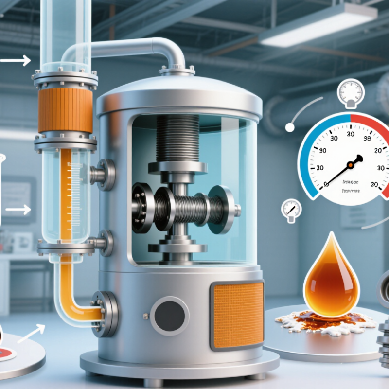
Define Feed Limits: Viscosity, Solids, Thermal Stability, and Boiling Range
How to Choose a VTA Thin Film Evaporator?
Define Feed Limits: Viscosity, Solids, Thermal Stability, and Boiling Range
Start with the feed, not the evaporator capacity. Record viscosity at the actual operating temperature, not only at room temperature. A liquid may pour easily at 25°C but become difficult near its concentration endpoint. High viscosity can weaken film distribution, increase motor load, and leave wet patches on the heated wall. Measure it across the expected temperature range.
Solids change the risk profile. Note particle size, concentration, abrasiveness, and the chance of deposits forming. A feed containing fine crystals may pass smoothly at the inlet but build a hard layer after several hours. Thermal stability needs equal attention. Compare product samples before and after controlled heating. Check color, odor, assay, and unwanted byproducts. Short residence time helps, but it cannot rescue a feed that decomposes at the wall temperature.
Boiling range also matters. A broad range may cause uneven evaporation and unstable vapor flow. Confirm the pressure-dependent boiling behavior with reliable laboratory data. Test the most concentrated feed, not only the easy starting mixture. This is where many selection sheets become too optimistic. I have seen clean pilot results fail after solids accumulated during a longer run. Include startup, shutdown, cleaning, and upset conditions in the review. Small details matter. Then match heat-transfer area, rotor clearance, seal materials, and vacuum capacity to the measured limits rather than guessed averages.
| Feed Parameter | Practical Screening Range | Primary Process Risk | ||
|---|---|---|---|---|
| Viscosity at Feed Temperature |
Low: <100 mPa·s Moderate: 100–1,000 mPa·s High: 1,000–10,000 mPa·s Very high: >10,000 mPa·s |
Poor wetting, unstable film formation, higher motor torque, reduced feed distribution, and possible product hold-up. | Low-to-moderate viscosity generally permits conventional feed distribution. High-viscosity feeds may require heated feed lines, larger clearances, higher torque capacity, slower rotor speed, and a positive-displacement feed system. | Measure viscosity over the actual feed-temperature range, not only at room temperature. Test the highest expected viscosity during start-up, concentration, and upset conditions. |
| Total Dissolved and Suspended Solids |
Low: 0–10 wt% Moderate: 10–40 wt% High: 40–60 wt% Very high: >60 wt% |
Fouling, crystal or particle deposition, blocked feed paths, increased abrasion, and a rapid rise in concentrate viscosity. | Moderate solids content is commonly manageable when the concentrate remains pumpable. High-solids feeds need strong film renewal, adequate discharge capacity, and sufficient clearance for particles or crystals. | Define particle size, hardness, crystal-forming tendency, and final concentrate solids. Confirm whether filtration, dilution, or a larger discharge path is needed. |
| Particle Size and Abrasiveness |
Fine particles: <100 μm Coarse particles: 100–500 μm Large or abrasive particles: >500 μm |
Rotor, wall, or distributor wear; localized plugging; non-uniform film thickness; and increased maintenance frequency. | Fine, non-abrasive solids are generally easier to process. Coarse or abrasive solids may require increased rotor clearance, wear-resistant surfaces, lower rotor speed, or upstream classification. | Provide particle-size distribution, hardness, shape, and concentration. Conduct a circulation and wear assessment using representative solids. |
| Thermal Stability |
Stable above operating temperature: >30°C margin Moderate margin: 10–30°C Limited margin: 0–10°C Decomposition below required temperature: unsuitable without process changes |
Color formation, oxidation, polymerization, loss of active components, decomposition, or formation of non-volatile residues. | A short-residence-time, high-vacuum design can reduce product exposure. Sensitive feeds may require lower wall temperature, higher vacuum, inert gas protection, rapid discharge, and minimized internal hold-up. | Establish the onset of degradation by validated thermal testing. Compare both temperature and residence-time effects under the intended vacuum and atmosphere. |
| Boiling Range at Operating Pressure |
Narrow range: <20°C Moderate range: 20–60°C Wide range: >60°C Thermally overlapping components: difficult separation |
Incomplete evaporation, entrainment, poor separation, excessive vapor load, or loss of valuable low-boiling components. | A narrow boiling range may support predictable evaporation. A wide or overlapping range requires staged operation, tighter vacuum control, multiple condensers, or a defined cut strategy. | Report boiling temperatures at the intended absolute pressure. Do not use atmospheric boiling points alone when sizing a vacuum thin-film evaporator. |
| Volatility of the Target Component |
Easily volatile: readily removed at selected vacuum Moderately volatile: requires controlled heating Low volatility: requires deeper vacuum or higher temperature |
Excessive energy demand, incomplete removal, product degradation, or vapor condensation in unintended locations. | The evaporator must provide adequate heat-transfer area, vacuum stability, vapor-line capacity, and condenser duty for the expected vapor load. | Define feed rate, target evaporation rate, absolute pressure, vapor composition, and required residual concentration before estimating area and utility loads. |
| Foaming and Entrained Liquids |
Low: stable liquid surface Moderate: intermittent foam High: persistent foam or gas release |
Vapor-line carryover, condenser contamination, unstable vacuum, reduced capacity, and off-spec product. | Foaming feeds may require a larger vapor disengagement zone, demister protection, lower vapor velocity, staged evaporation, or controlled antifoam use where compatible with the product. | Perform a vacuum heating and foaming test with representative feed composition, including dissolved gases and surfactants. |
| Concentrate Discharge Viscosity |
Pumpable: <1,000 mPa·s Difficult: 1,000–10,000 mPa·s Highly difficult: >10,000 mPa·s or paste-like |
Discharge blockage, unstable level control, insufficient residence-time control, and excessive torque at the outlet. | The concentrate often determines the practical operating limit more than the initial feed. High-viscosity discharge may need heated outlets, larger discharge ports, specialized pumps, or lower final concentration. | Measure concentrate viscosity at the expected discharge temperature and solids level. Include start-up, shutdown, and maximum-concentration conditions. |
| Water or Solvent Content |
High volatile load: >50 wt% volatile solvent Moderate load: 10–50 wt% Low load: <10 wt% |
Excessive vapor load, unstable pressure, condenser overload, solvent losses, and potential flammability hazards. | High volatile loads require adequate vapor-handling capacity, compatible seals and materials, correctly sized condensers, and suitable hazardous-area controls where applicable. | Specify solvent identity, vapor pressure, latent heat, non-condensable gas content, and required recovery rate. Confirm compatibility with the vacuum system and condenser. |
| Recommended Initial Design Margin |
Capacity margin: typically 10–25% Thermal margin: maintain a defined degradation margin Torque margin: verify at maximum viscosity |
Loss of capacity during seasonal changes, feed variability, fouling, increased viscosity, or operation near mechanical limits. | A design based only on nominal feed conditions can be undersized. Mechanical, thermal, vacuum, and discharge limits should all be checked independently. | Use minimum, nominal, and maximum feed cases for sizing. Confirm the final design with pilot testing or representative process trials. |
Related Posts
-
What Is a Wiped Film Evaporator and How Does It Work?
-
2026 Best Agitated Evaporator Suppliers for Global Buyers
-
How to Choose a China Agitated Thin Film Evaporator?
-
How to Choose the Best Wiped Film Evaporator in 2026?
-

What is a Thin Layer Evaporator and How Does It Work
-
10 Essential Tips for Using a Film Evaporator Effectively